Rubik's Cube Part 3
15 Jul 20232 years from the last Cube Project post, some of you might be expecting this third edition to come out sooner or later.
The Idea
So far, I have had a single project related to the cube every single year; the Speedcube Method Efficiency Analysis project in first year as part of Science One, and the Cube Timer project in second year as part of CPSC 210. Naturally, it would be ingenious to continue the theme and work on a cube-related project in third year. As such, as part of PHYS 319, an electronics lab course, I have chosen to build a microcontroller-based robotic Rubik’s Cube solver.
The Parts
Stepper Motor
Since we would need to individually move the 6 faces of the cube, we would need motors that have precise positional control, with the additional benefit that they can turn an indefinite amount in any direction. Our choice is the use 6 stepper motors, specifically the NEMA 17 bipolar stepper motors, which you can often find for a cheap price on Amazon.
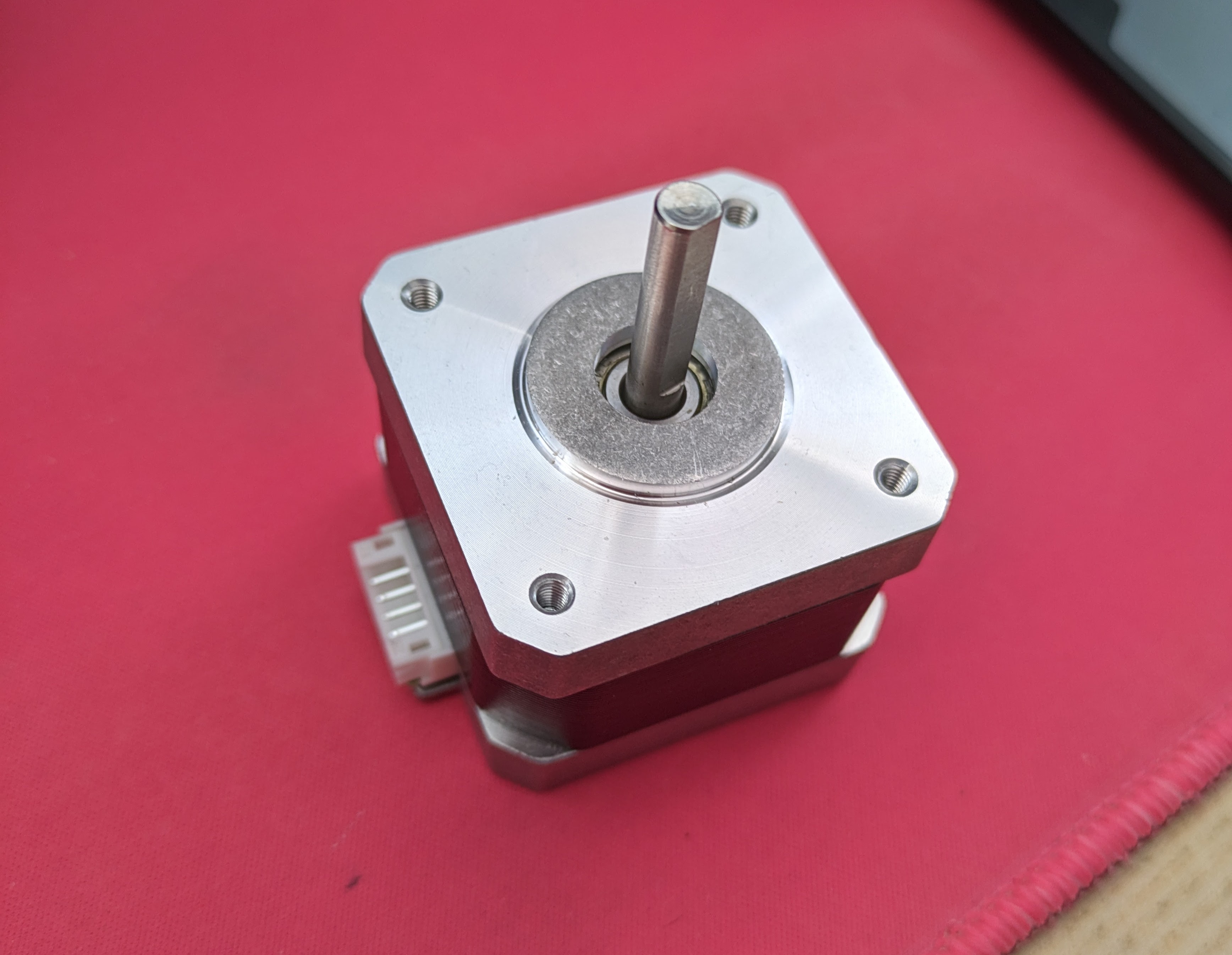
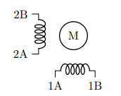
Bipolar stepper motors operate on two coils, and given a current alternately between the coils, we can drive the motor shaft (a permanent magnet) to rotate a precise angle, and in our case exactly 1.8°.
Stepper Motor Driver
However, the delicate task of controlling a single stepper motor requires four output pins on the microcontroller, which adds up to 24 output pins to control six motors, taking up a significant amount of the total available pins. Therefore, we delegate the task of manouvering a stepper motor to a specialized integrated circuit, the stepper motor driver, which requires significantly fewer pins to control..
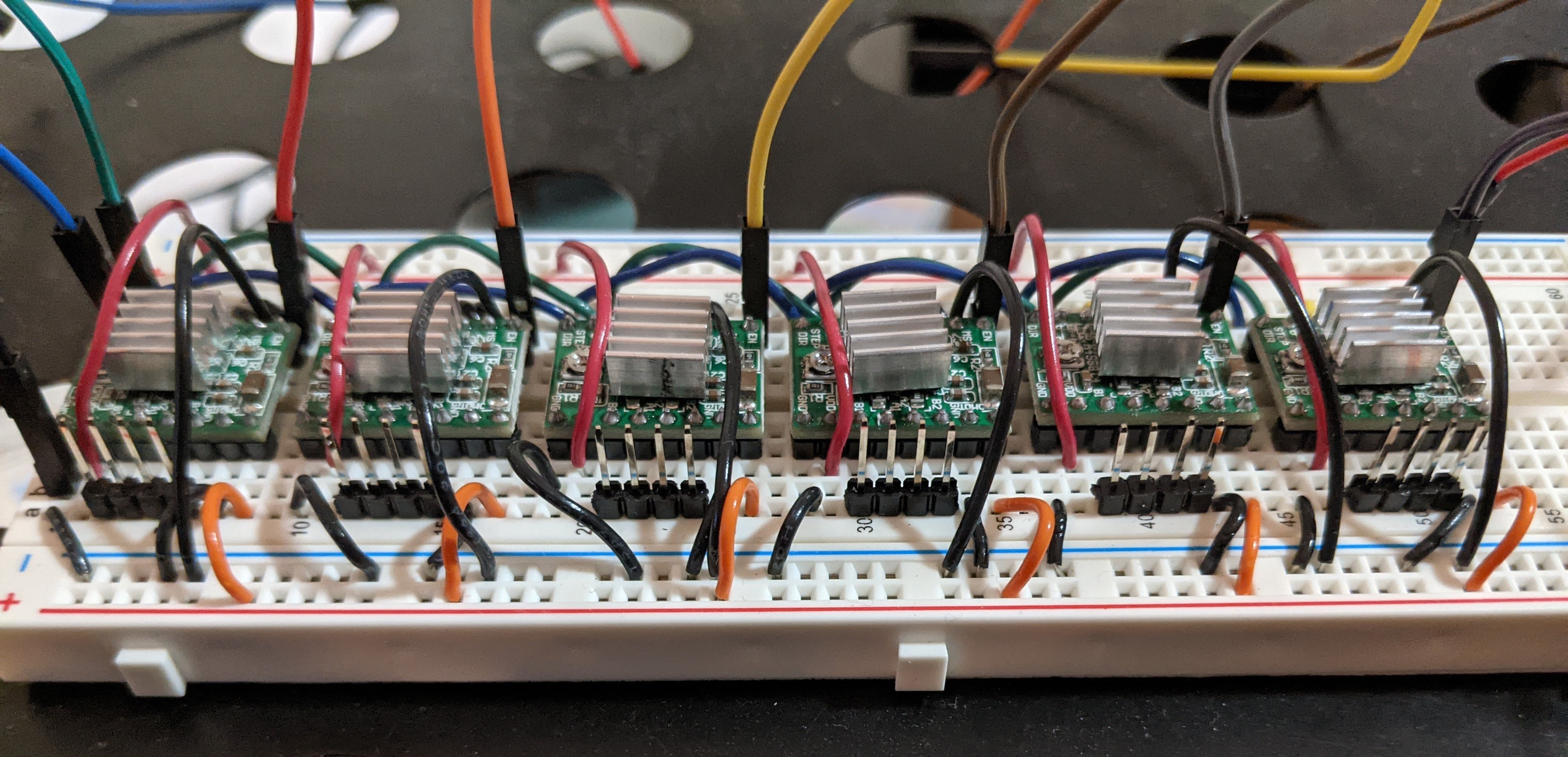
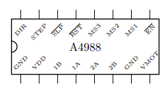
The cheapest and most common drivers found on Amazon are the A4988, which we need one each for the six stepper motors. Now they would only require 3 signals each to control, 2 of which can be the same signal between all drivers.
Coupling Mechanism
Now that we have the thing that moves (the motor) and the thing that is about to be moved (the cube), we need to figure out a way to connect those two parts. Since there is no premade component that interfaces a cube and a motor, we must therefore design our own.
To successfully turn the face of a cube, we merely need to turn the center of the cube. Our mechanism relies on the cube having detachable center tiles, which we can slot in our mechanism that grapples on it.
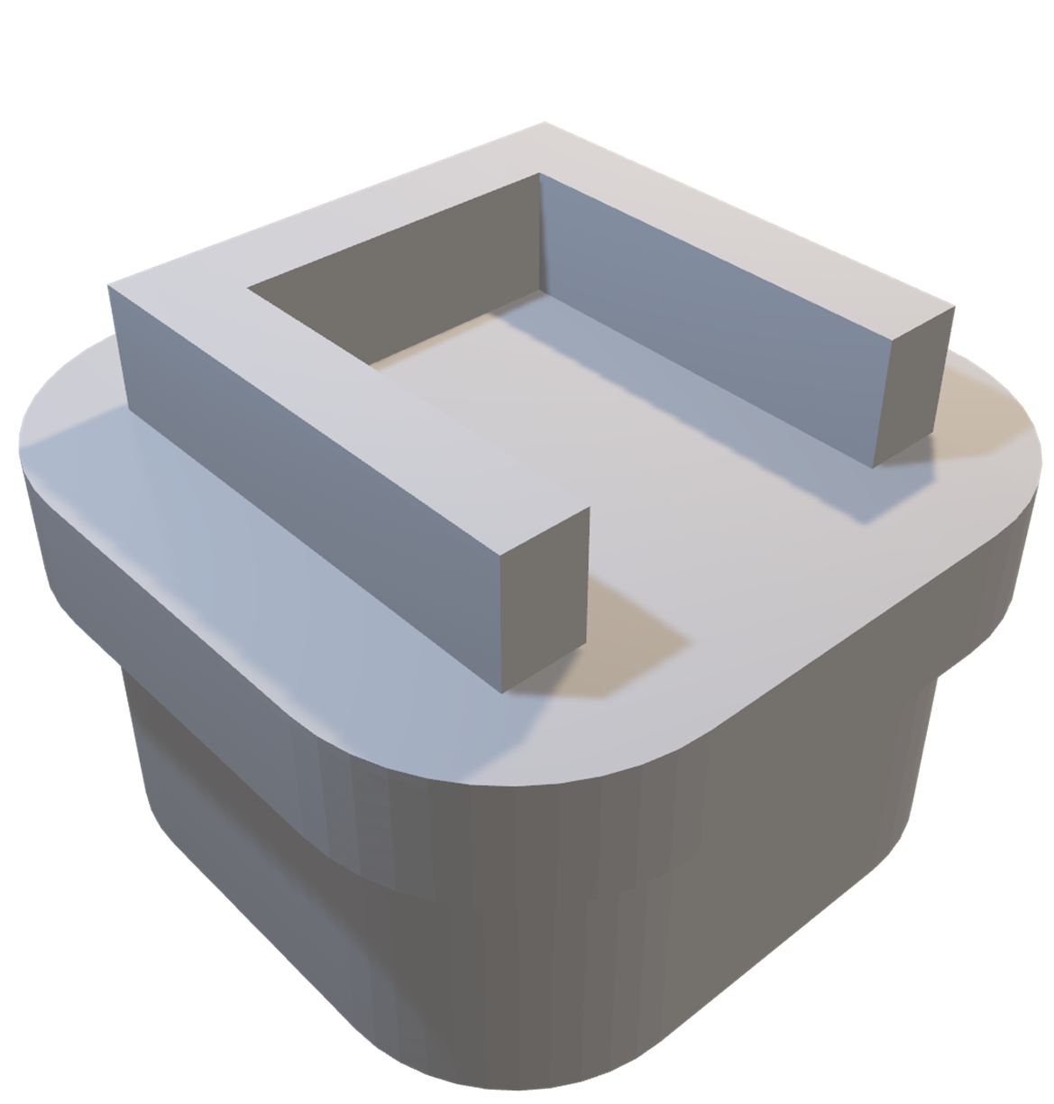

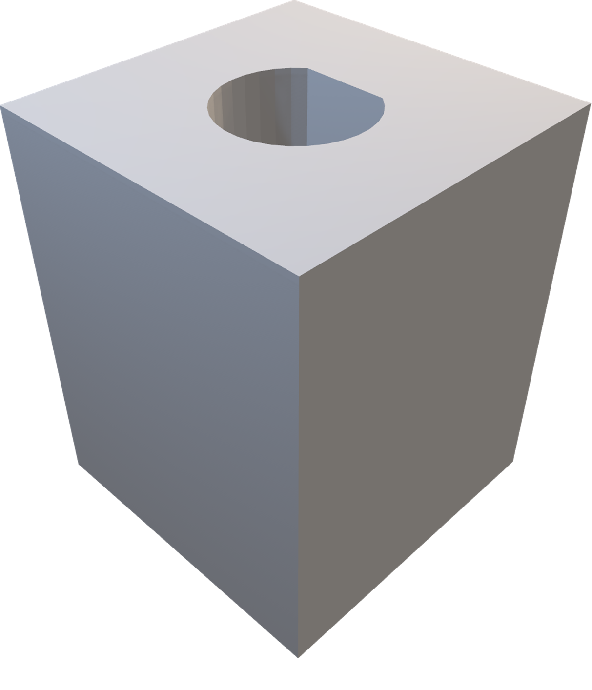
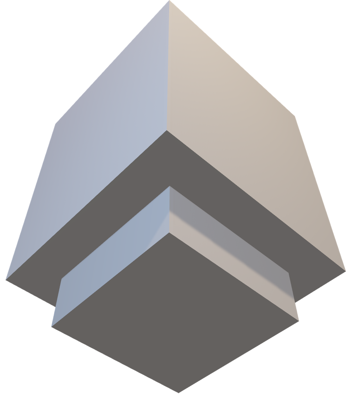
This cubeside part must be connected to the motorside part such that as the motor shaft rotates, the parts rotate along with it. We have designed these two parts to be separable so that we gain the possibility and convenience of removing the cube itself without disturbing the motor setup.
A small thank you to Morgan for lending me his 3D printer, which made the production of these parts possible.
Power Supply
The next issue is with a power supply. Since the logic voltage supply is usually either 3.3V or 5V, while the motor voltage supply needs to be above 8V, we must use different power supplies for the logic and motor circuits. As motors can often draw a lot of current and power, to minimize heat dissipation, we have chosen the logic voltage as 3.3V, and the motor voltage to be 12V. Although the motors themselves are rated at 7.3V, we can tune the potentiometer on the driver itself such that no excessive voltage or current will go through the motor.
The choice of 12V is also partly due to the cube itself. Inside every single center, there is a tunable spring. If we let the spring be more loose, then we would require a lower torque to overcome static friction, and hence the motor would not require as much power and voltage; however, the faces of the cube will cam outwards as we rotate them, which might lead to small undesired movements of the cube itself, and the faces might get stuck in the middle of a rotation, potentially leading to a rapid disassembly of both the cube and the machine. On the other hand, to prevent that from happening, we woudl require a higher torque to overcome the higher static friction, and hence the motor would require more power and higher voltage. Our final choice of 12V and 1.3A is a good balance.
Before successfully sourcing for a potential power supply, I have been using the AC to 12V that came with the Wi-Fi router at home. Luckily, I had found an identical power supply in Best Buy merely days before the actual presentation for this project, as otherwise my home would have to go without internet every time I try to power up my robot.
Structure
To package together all the components, we must build a frame. We used a Lego set that is readily available, which allowed for quick prototyping of different structures at the cost of a small amount of precision of placements.
The other obvious choice for the material for the structure would be laser-cut acrylic sheets. This would have been the preferred way to build the structure, as I am familiar with laser cutters from grades 7 & 8; however, I did not know that we had access to the laser cutters, which were just situated in the engineering physics lab next door.
The Logic
Microcontroller
As the microcontroller itself lacks the computing power to perform a search to find a solution, we can outsource this to a host computer, so the only task the microcontroller really needs to perform is to receive instructions from the host computer and then execute those instructions on the motors.
We have chosen to use the universal asynchronous transmitter-receiver (UART) protocol, and as its name suggests, is a universal protocol for two-way communication. Both sides can initiate a message transmission, which is a desired function, as we want the host computer to raise an interrupt flag on the microcontroller side when we send in a move instruction, allow the microcontroller to perform that move, and let it raise an interrupt flag on the host computer in return as to signal that it has completed the move, and is ready to receive another instruction.
As UART can only send one byte at a time, we can encode information about which motor needs to move and the amount it needs to move by in eight bits, or two hexits. We let the most significant hexit range from 0 to 5, representing the pin that we will enable, and therefore the motor that we will activate; and we let the least significant hexit range from 0 to 2, representing 90° clockwise, 180°, and 90° counterclockwise movements respectively.
The typical cycle of communication looks like the following:
- Microcontroller receives a single instruction via UART.
- Decodes it into our desired motor and movement.
- Activate corresponding motor and change directions.
- Step the motor the desired number of times.
- Disable motor.
- Signal to host computer that movement is complete via UART.
Host Computer
However, we must generate those set of moves
before we can send it to the microcontroller.
This is written in Python,
as Python has a package for serial port communication via UART,
and also a twophase package for Rubik’s cube solving.
All we have to do is to input the 54 colours of the cube,
allow time for the computer to find a solution,
encode these moves into hexits,
and then send them one by one via UART.
The Algorithm
Well then, one might ask, what algorithm might we want to use to solve the cube? We already had one such discussion in part 1, but that mostly pertains to human solvers, which are very limited in memory and search speed. We could try to implement CFOP or Roux deterministically as we did back then, but number of lookup tables involved there are minimal, which implies we would not be taking the most advantage of the computer.
We now turn our attention to Kociemba’s algorithm. Created by Herbert Kociemba in 1992, this is an algorithm that solves the Rubik’s cube in two phases. Let us first define two groups, $G_0 = \langle U,D,L,R,F,B \rangle$ and $G_1 = \langle U,D,L^2,R^2,F^2,B^2 \rangle$. For those unfamiliar with abstract algebra, we can treat $G_0$ as the set of cube states that we can get to (note that we are equating sequence of moves applied to starting cube state to the cube state itself) by applying any composition of the moves ${U,D,L,R,F,B}$ to the cube (i.e. all possible states); and similarly, $G_1$ is also a set of cube states, but given its generating set of moves are more restrictive, it is a smaller set of possible states, and in fact is a normal subgroup of $G_0$. An easy description of $G_1$ would be that the orientation of all edges and corners are solved, and the 4 edges between the $U$ and $D$ slices are within that slice.
Side note. As we noted earlier, we are treating the moves and the cube states as the same exact group. Formally speaking, the group of moves $G_0$ acts on a set $G_0$ of all possible legal cube states, with correct spin and parity. Choosing the starting state of a solved cube $1 \in G_0$, the orbit of $1$ under $G_0$, defined as the set of all possible cube states in $G_0$ (the set) that we can obtain by applying the moves in $G_0$, must be the entire set $G_0$.
The first phase of the algorithm searches through the coset space $G_0/G_1$, that is, trying to find a solution that gets us to a cube state in $G_1$. By exhausting through all possibilities in this state, we can generate lookup tables that also serve as a heuristic function for the search function, which helps us evaluate which moves we should try first. Moreover, the generated lookup tables allow us to prune away large amounts of incorrect moves, reducing the computation time at the cost of memory.
The second phase of the algorithm now continues the search using only the moves ${U,D,L^2,R^2,F^2,B^2}$, permuting through the possible locations for each piece. Notice that we do not terminate the algorithm at the first complete solution; we will now continue to search the second phase by using less optimal solutions in the first phase. Suppose we originally needed $n$ moves in the first phase, and $m$ moves in the second phase. After we have found this solution, we will now proceed to a suboptimal solution of $n+1$ moves in the first phase, and attempt to find a solution of less than $m-1$ moves in the second phase. We repeat this process until $m=0$, which implies we have found an optimal solution.
As we only need to find a relatively good solution and not the absolute optimal one, we can terminate the search early. This is a balance between computation time and solve time.
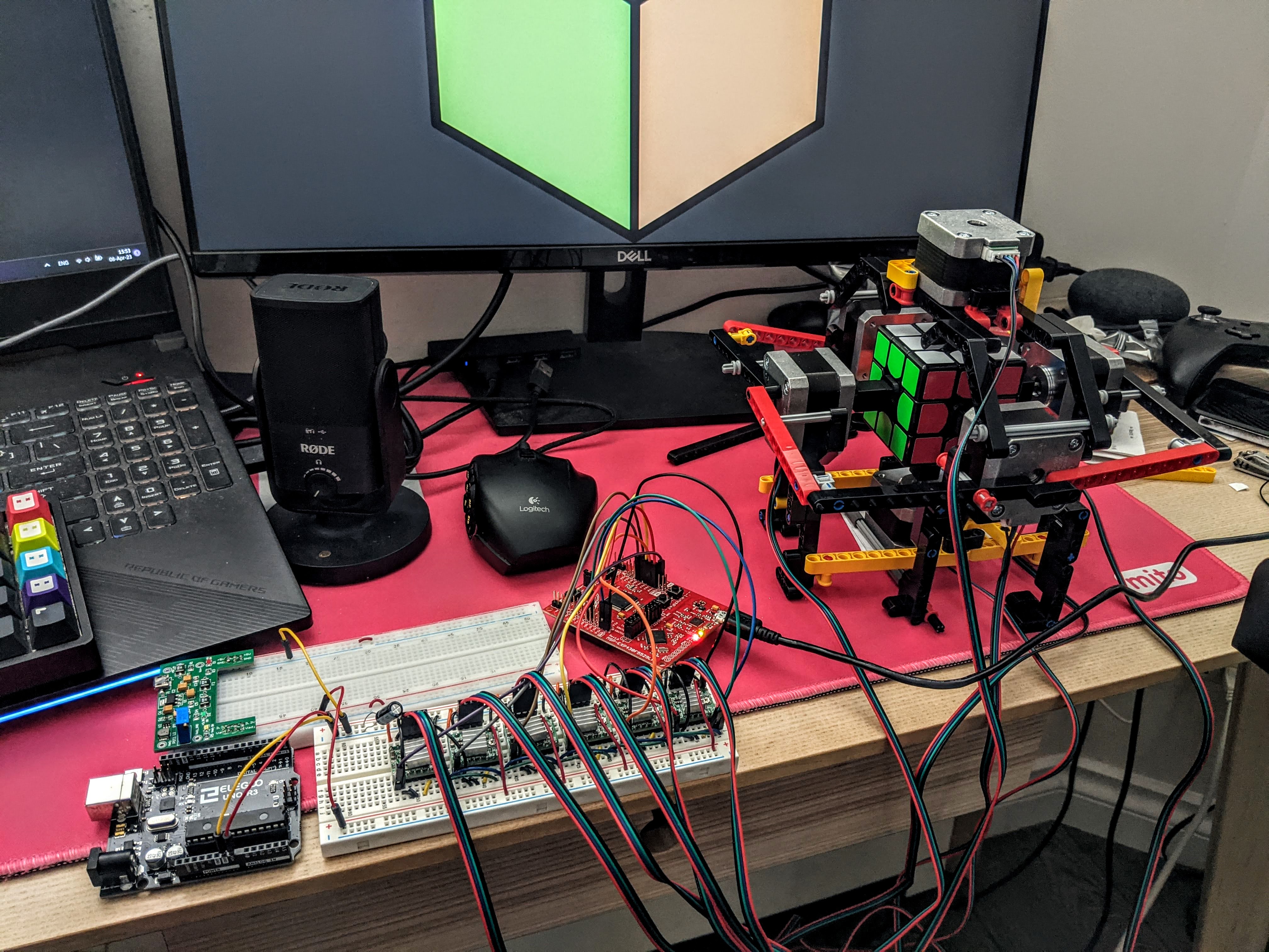
End Result
After assembling everything together, the final product is one such video.